Electric Circuits
Matthew Williams
||5 min readAmmeterCSEC PhysicsElectric CircuitsPaper 01Paper 02ParallelResistanceSection DSeriesVoltmeter
Series and parallel circuits, equivalent resistance formulas, ammeter and voltmeter placement, circuit analysis, and cells (primary versus secondary).
Circuit Symbols and Diagrams
Standard circuit diagrams use internationally recognised symbols. Key components and their symbols:
| Component | Symbol description |
|---|---|
| Cell | Long line (positive) + short line (negative) |
| Battery | Multiple cell symbols in series |
| Switch | Gap that can be bridged |
| Resistor | Rectangle |
| Variable resistor | Rectangle with diagonal arrow |
| Lamp | Circle with cross |
| Ammeter | Circle labelled A |
| Voltmeter | Circle labelled V |
| Fuse | Rectangle with line through it |
| Diode | Triangle pointing to vertical line |
Series Circuits
In a series circuit, components are connected end-to-end in a single loop:
- The same current flows through every component.
- The total p.d. of the supply equals the sum of the p.d.s across each component.
- The equivalent (total) resistance is the sum of all resistances:
Removing or breaking any component breaks the entire circuit.
Parallel Circuits
In a parallel circuit, components are connected across common junction points (they share the same two nodes):
- The p.d. across each branch is the same (equal to the supply p.d.).
- The total current from the supply equals the sum of currents through each branch.
- The equivalent resistance satisfies:
The equivalent resistance of a parallel combination is always less than the smallest individual resistance. Adding more parallel branches reduces the overall resistance.
Measuring Current and Voltage
Ammeters measure current and are connected in series with the component being measured (so the same current flows through both).
Voltmeters measure p.d. and are connected in parallel across the component (so they share the same two nodes). A voltmeter must have very high resistance so it does not divert significant current.
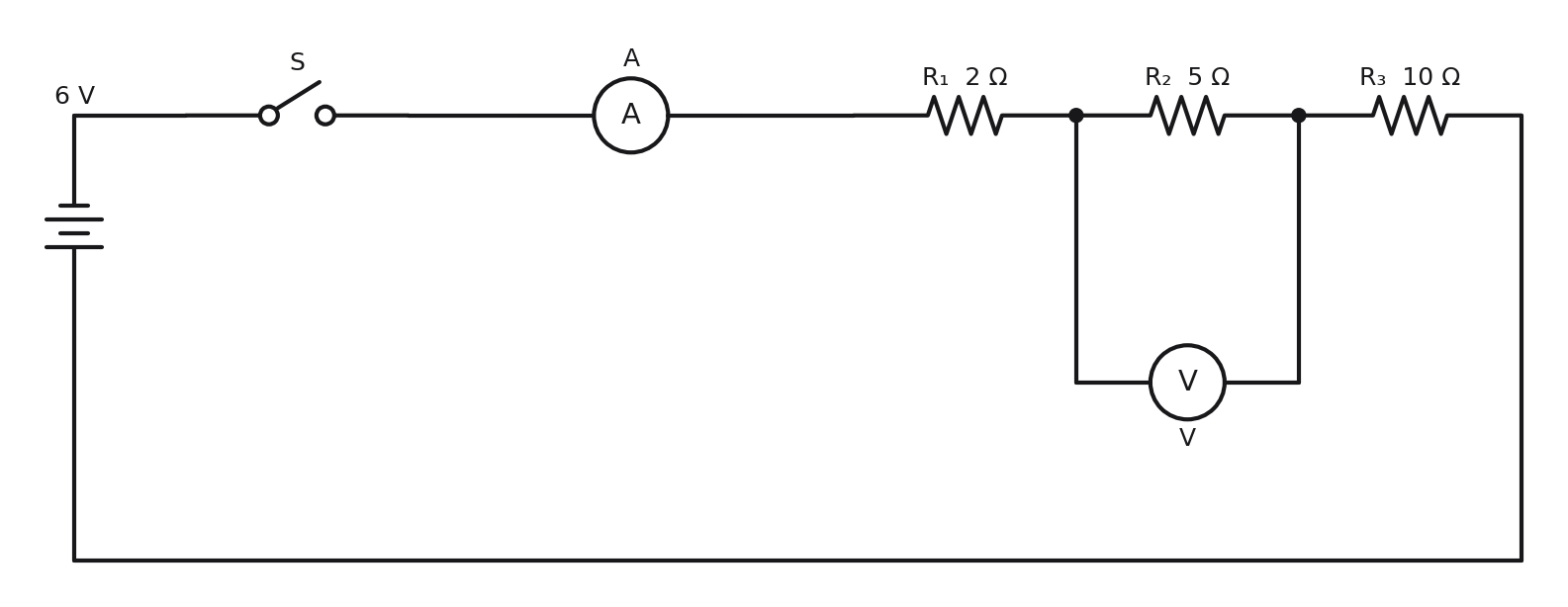
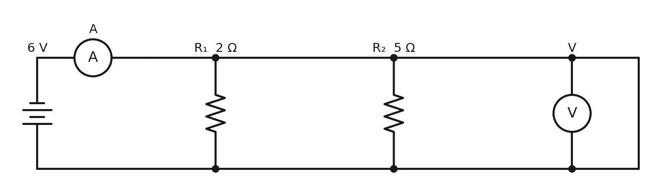
ExampleSeries and parallel resistances (2019 Paper 02, Q5)
Three resistors of 2 Ω, 5 Ω, and 10 Ω are connected first in series, then in parallel to a 6 V supply.
Series equivalent resistance:
Parallel equivalent resistance:
Total current from 6 V supply in parallel circuit:
Cells: Primary and Secondary
| Type | Description | Examples |
|---|---|---|
| Primary cell | Cannot be recharged, chemical energy converts to electrical energy until exhausted | Zinc-carbon, alkaline batteries |
| Secondary cell | Can be recharged by passing current through it in reverse | Lead-acid (car battery), lithium-ion (phones) |
Cells connected in series add their EMFs. Cells connected in parallel keep the same EMF but can supply more current (longer life).
Exam Tip
For parallel resistance calculations, find first by adding the reciprocals, then take the reciprocal of the total. A common error is forgetting to take the final reciprocal.
When two resistors are in parallel, the shortcut formula is: .
An ammeter goes in series; a voltmeter goes in parallel. Getting this wrong in a diagram loses marks.